
How they work
Electric presses represent the pinnacle of the Alfamatic product range: ultra-precise, reliable and versatile machines. They deliver high thrust force (up to 300 kN) and precise, instant machining control.
An ideal solution for a wide variety of industrial applications..
Take a look at the video down below to see how they work.

High Flexibility of Applications

Bending

Drawing

Keying

Assembly

Clinching

Trimming

Chamfering

Marking

Straightening

Riveting

Pressing

Cutting

Compressing
Why you should choose Alfamatic electric presses

Active control of the process
Movements are continuously monitored in terms of acceleration, speed, and position. Active position control ensures high stopping-point accuracy, which can be further enhanced with the use of an external micrometer-grade position transducer.
High productivity
The rod excursion is minimized: the cycles are accelerated and the processing times are reduced.
Application flexibility
Complex machining cycles are easily programmable, with individually saved and fully independent parameter sets.
Long duration
The synergy of high-performance mechanical components guarantees extended durability, even in demanding operating environments.
Low management cost
Energy consumption is limited to the processing stage only, optimizing energy efficiency.
THE ELECTRIC CYLINDER
The electric cylinder —featured in all four versions of Alfamatic presses— is the core of the system, delivering a force ranging from 0.05 kN up to 300 kN.
Thanks to its advanced technology, the cylinder offers high thrust, exceptional quietness, and minimal vibration.
Its maximum force and speed depend on the gear ratio, which, in some cases, allows for future modifications to the press — either to increase or reduce its output force.


Based on planetary roller technology (the best in this range), the cylinder allows you to perform the heaviest machining operations with centesimal precision.

PRESS-RIGHT
It is the instrument that supervises the functioning of the press and guarantees the quality control on 100% of the production. The brain of the system.
It is interfaced with a resolver type position transducer and a strain gauge force transducer (ideal for pressing operations).
It continuously monitors the position/force curve, ensuring it remains within a predefined control band that is precisely set for the application.
It directly controls motor movement, with precise real-time monitoring of both force and position values.
The Structures
The electric presses are available in three different configurations:

C-Frame Structure
Monolithic C-shaped structure with low bending.
It is the most suitable structure when space is needed in a transversal sense.
In steel Fe 430 B UNI 7070.
The surfaces are protected by high resistance multilayer paint.
Available with thrust forces up to 100 kN.

Structure with Pillars
Low flex 4 column structure.
Structure in steel Fe 430 B UNI 7070.
Upper and lower plates protected by burnishing treatment.
Thick chromed columns.
Available with thrust forces up to 300 kN.

Structure with Pillars and Plate
Low-flex 4-post structure and guided movable intermediate plate.
Structure in steel Fe 430 B UNI 7070.
Upper, lower and intermediate plates protected by burnishing treatment.
Thick chromed columns.
Intermediate plate equipped with pneumatically operated fall arrest device.
Available with thrust forces up to 300 kN.
Safety Guards

Alfamatic electric presses comply with the current strict CE safety regulations.
They are equipped with intangible light curtains and Lexan® perimeter protections.
A further pair of photoelectric barriers, positioned on the upper part of the work area, free from both visual obstacles and accessibility to the piece.
The press is activated by pressing the two-hand control.
Once the cycle has started, the operator can release the buttons and the press will continue autonomously until the pre-established parameters for the execution of the piece are reached.

Alfamatic electric presses comply with the current strict CE safety regulations.
The CA version is equipped with a pneumatically operated mobile frontal gate and Lexan® perimeter guards.
This type of protection is particularly suitable if the operation to be performed presents the possibility of projection of the piece during the pressing phase.
The press is activated by pressing the two-hand control.
Once the cycle has started, the operator can release the buttons and the press will continue autonomously until the pre-established parameters for the execution of the piece are reached.
Main Features

Main Features

Main Features
Equipped with adjustable feet (height to be determined when ordering).
Incorporated in the right side of the table, easily accessible for inspection and maintenance.

To operate the press and control the operating parameters. It is equipped with touch buttons for maximum ease of use:
- • Two-hand touch control
- • Press reset button
- • Emergency stop button
- • Safety selector

In steel Fe 430 B UNI 7070 with ground surface. Equipped with T-slots for fixing the mold.

With perimeter protections in Lexan® and front part with free access, protected by immaterial barriers (photo-electric; in compliance with current CE regulations).
- • Upper light curtain
- • Lexan® perimeter protection
- • Side light barrier
- • C-framed, monolithic, in steel Fe 430 B UNI 7070.
- • With 4 columns with upper and lower plates in Fe 430 B UNI 7070 steel and supporting columns in chromed C45 steel.
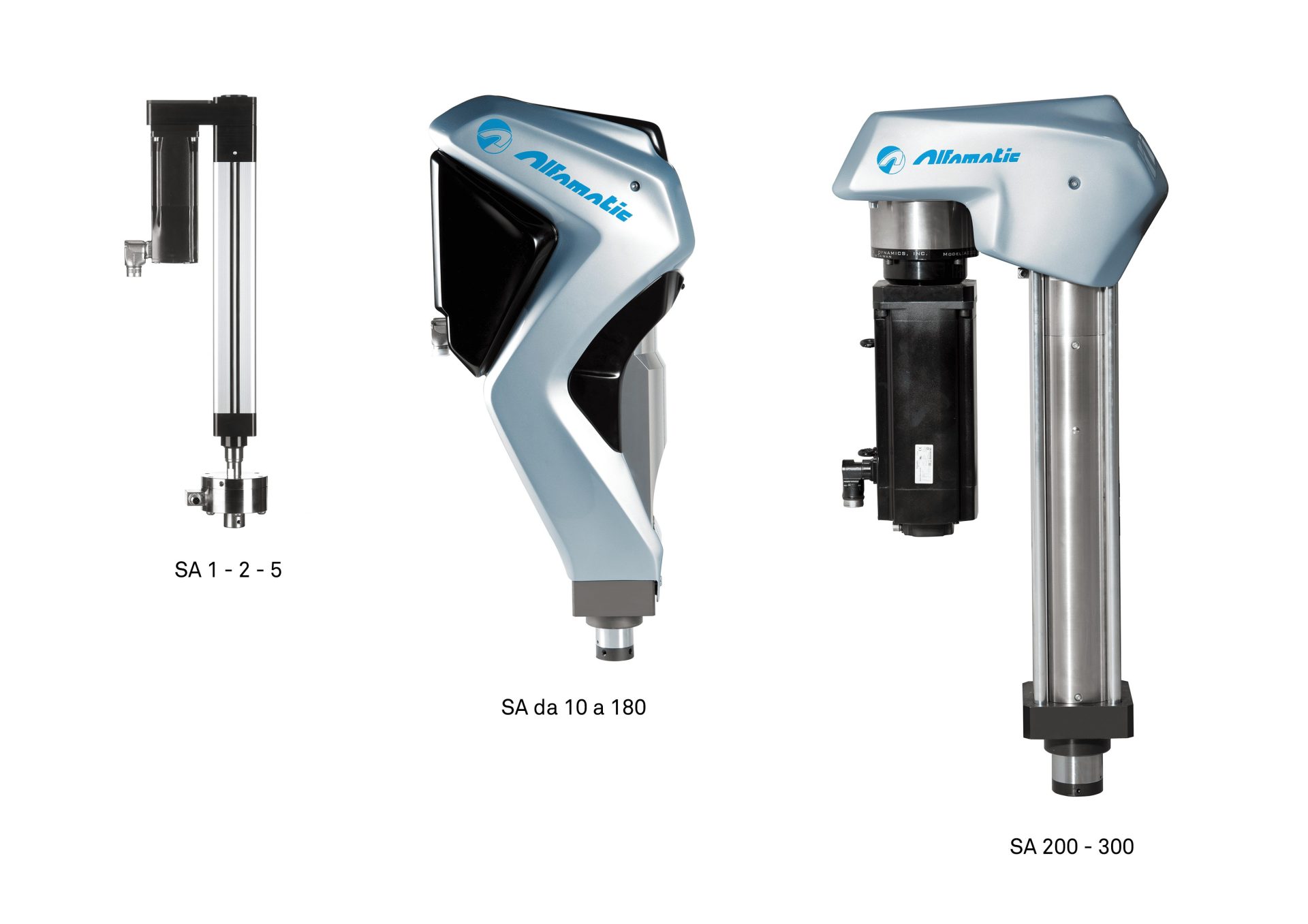
Available with thrust force from 1 to 300kN. Depending on the size, equipped with roller or recirculating ball screw. Models 1-2-5 are equipped with an external load cell, placed on the end of the rod.
Accessories and Options
External Load Cell
The external HPT load cell allows precise measurement of low forces, extending the versatility of Alfamatic electric cylinders even more.

External Micrometric Probe
It enables micrometric precision measurement of the tool’s true position relative to a reference point on the workpiece, eliminating inaccuracies caused by structural play and deformation.

Traffic Light Access to Work Area
A light indicator shows when the press is at rest and the work area is safely accessible. This prevents unnecessary machine stops caused by accidental activation of safety barriers during rod movement.
Lighting
For a better visibility of the work area.

Lubricating Grease
Specific lubricating grease for presses with planetary roller screws.
Grease Pump
It enables the addition of grease inside the electric actuator nut throught the greasing hole.

RFID
RFID device for the automatic identification of the processing code.
Upon reading the RFID tag, the Press-Right system autonomously loads the corresponding processing recipe and configures the press parameters accordingly, eliminating the need for manual setup and minimizing the risk of configuration errors.

Range and Technical Specifications
| EP1 | EP2 | EP5 | EP10 | EP15 | EP25 | EP50 | EP70 | EP100 | EP120 | EP150 | EP180 | EP200 | EP300 | |
|---|---|---|---|---|---|---|---|---|---|---|---|---|---|---|
| Nominal Force (kN) | 1 | 2 | 5 | 10 | 15 | 25 | 50 | 70 | 100 | 120 | 150 | 180 | 200 | 300 |
| Maximum Speed (mm/s) | 250 | 250 | 250 | 250 | 180 | 100 | 250 | 180 | 100 | 125 | 105 | 83 | 150 | 100 |
| Repeatability at Constant Load (± mm) | 0,04 | 0,01 | ||||||||||||
| Measured force accuracy (± F.S.) | 0,5% | 0,5% | 0,5% | 0,5% | 0,5% | 0,5% | 1% | 0,7% | 0,5% | 0,5% | 0,5% | 0,5% | 0,5% | 0,5% |
| Anti-rotation system accuracy | 0,7° | 1° | ||||||||||||
| Direction of Measurement | bi-direction (compression and traction) | traction | ||||||||||||
| Stroke (mm) | 280 | 280 | 280 | 300 420 | 300 420 | 300 420 | 250 420 | 250 420 | 250 420 | 250 420 | 250 420 | 250 420 | 420 | 420 |
| Force Sensor (load cell) | external | internal | ||||||||||||
| Parking brake | standard | |||||||||||||
| Screw Construction Technology | recirculating balls | satellite rollers | ||||||||||||
| Screw Life Span (in millions of cycles) | 20 | 20 | 20 | 30 | 15 | 15 | 30 | 15 | 10 | 30 | 20 | 15 | 30 | 15 |
| Measurement and Control Instrument | Press-Right | |||||||||||||
1 kN
0,5% F.S.
280 mm
20 Mio
250 mm/s
0.7°
External Load Cell
Standard
0,04 mm
Direction of Measurement bi-directional (compression and traction)
Recirculating Balls
Press-Right System
2kN
0,5% F.S.
280 mm
20 Mio
250 mm/s
0.7°
External Load Cell
Standard
0,04 mm
Direction of Measurement bi-directional (compression and traction)
Recirculating Balls
Press-Right System
5 kN
0,5% F.S.
280 mm
20 Mio
250 mm/s
0.7°
External Load Cell
Standard
0,04 mm
Direction of Measurement bi-directional (compression and traction)
Recirculating Balls
Press-Right System
10 kN
0,5% F.S.
300 / 420 mm
30 Mio
250 mm/s
0.7°
Internal Load Cell
Standard
0,01 mm
Direction of Measurement bi-directional (compression and traction)
With Satellite Rollers
Press-Right System
15 kN
0.5% F.S.
300 / 420 mm
15 Mio
180 mm/s
0.7°
Internal Load Cell
Standard
0,01 mm
Direction of Measurement bi-directional (compression and traction)
With Satellite Rollers
Press-Right System
25 kN
0,5% F.S.
300 / 420 mm
15 Mio
140 mm/s
0.7°
Internal Load Cell
Standard
0,01 mm
Direction of Measurement bi-directional (compression and traction)
With Satellite Rollers
Press-Right System
50 kN
1% F.S.
250 / 420 mm
30 Mio
250 mm/s
0.7°
Internal Load Cell
Standard
0,01 mm
Direction of Measurement bi-directional (compression and traction)
With Satellite Rollers
Press-Right System
70 kN
0,7% F.S.
250 / 420 mm
15 Mio
180 mm/s
0.7°
Internal Load Cell
Standard
0,01 mm
Direction of Measurement bi-directional (compression and traction)
With Satellite Rollers
Press-Right System
100 kN
0,5% F.S.
250 / 420 mm
10 Mio
100 mm/s
0.7°
Internal Load Cell
Standard
0,01 mm
Direction of Measurement bi-directional (compression and traction)
With Satellite Rollers
Press-Right System
120 kN
0,5% F.S.
250 / 420 mm
30 Mio
125 mm/s
0.7°
Internal Load Cell
Standard
0,01 mm
Compression
With Satellite Rollers
Press-Right System
150 kN
0,5% F.S.
250 / 420 mm
20 Mio
105 mm/s
0,7°
Internal Load Cell
Standard
0,01 mm
Compression
With Satellite Rollers
Press-Right System
180 kN
0,5% F.S.
250 / 420 mm
15 Mio
83 mm/s
0,7°
Internal Load Cell
Standard
0,01 mm
Compression
With Satellite Rollers
Press-Right System
200 kN
0,5% F.S.
420 mm
30 Mio
150 mm/s
1°
Internal Load Cell
Standard
0,01 mm
Compression
With Satellite Rollers
Press-Right System
300 kN
0,5% F.S.
420 mm
15 Mio
100 mm/s
1°
Internal Load Cell
Standard
0,01 mm
Compression
With Satellite Rollers
Press-Right System
Download
CATALOGO EP - ESP
16/10/2025
CATALOGUE EP-FRA
16/10/2025
Electric press manual - eng
21/02/2025
Electric press manual - ita
20/02/2025
EP catalog - eng
26/02/2024
EP catalog - ita
13/03/2025
Press-Right PE User Manual - eng
10/09/2025
Press-Right PE User Manual - ita
10/09/2025