

PRESSES


How Pneumo-Hydraulic Lever Presses work
The MOP series presses work with compressed air up to 6 bar.
Thanks to the built-in pressure multiplier, they can develop high thrust forces without effort for the operator.
They combine the ease of use of a rack press with the thrust force of a hydraulic press.
High Flexibility of Applications


Bending


Drawing


Keying


Assembly


Clinching


Trimming


Chamfering


Marking


Straightening


Riveting


Pressing


Cutting


Compressing
The work phases
- press at rest
-
Approach strokeo
The lever activates the descent of the stem via a pinion/rack device, allowing the tool to be brought closer to the piece to be worked. -
ENGAGEMENT STROKE
Subsequent lowering of the lever engages the force intensifier. -
pressing stroke
By pressing the side button, the pneumo-hydraulic intensification carries out the working stroke.


Why choose Alfamatic hydropneumatic presses


The combination of approaching the piece with a manual lever and the pressing force generated by a separate and independent pressure multiplier, gives the MOP presses a series of advantages:
Easy to use
The approach to the piece to be pressed is achieved by simply lowering the lever, without effort. The hydraulic power is self-switching and effortless for the operator
Control of the point of contact
The operator, during the descent of the rod, can precisely control the point of contact with the piece and easily and precisely center himself on it.
Silence
The noise of the press is limited to the development phase of the pressing stroke and falls within the low limits established by law.
Economy
The phases of approach to the piece and return are completely manual and controlled by the operator. This translates into limited energy consumption.


The Advantages of Manual Operation
The combination of approaching the piece with a manual lever and the pressing force generated by a separate and independent pressure multiplier, gives the MOP presses a series of advantages:
-
Ease of use
The approach to the piece to be pressed is achieved by simply lowering the lever, without effort. The hydraulic power is automatically switched and effortless for the operator. -
CONTACT POINT CONTROL
The operator, during the descent of the rod, can precisely control the point of contact with the piece and center himself on it with ease and precision. -
Silence
The noise of the press is limited to the development phase of the pressing stroke and falls within the low limits established by law. -
Economy
The phases of approach to the piece and return are completely manual and controlled by the operator. This translates into limited energy consumption.
The Structures
The manual presses are available in 3 structure configurations:


Structure with Increased Light
Configuration suitable for machining pieces of greater height


Structure with Increased Light and Reach
Configuration suitable for machining tall pieces and with a bulky base
Main Features
Main Features
Main Features


Engages left hand when operating the lever. Available with push or touch actuation.


The operating and adjustment parameters of the machine are available on the front panel:
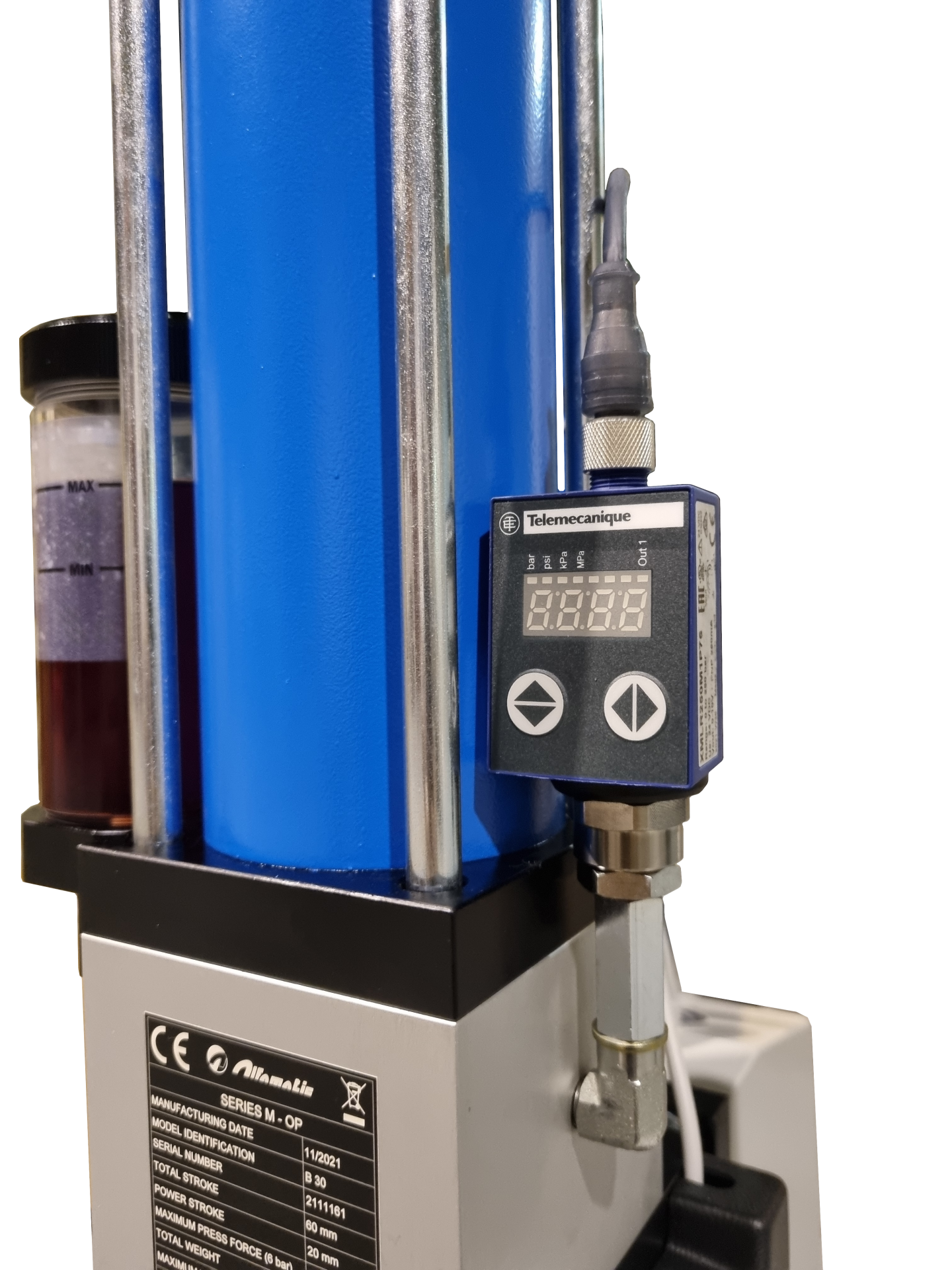

Mold support plate in steel Fe 430 B UNI 7070 with ground surface. Equipped with T-slots for fixing the mold.


The shoulder is provided with holes that allow the head unit to be lowered, reducing the working width (for sizes 07, 15 and 30 with total stroke 60 mm).
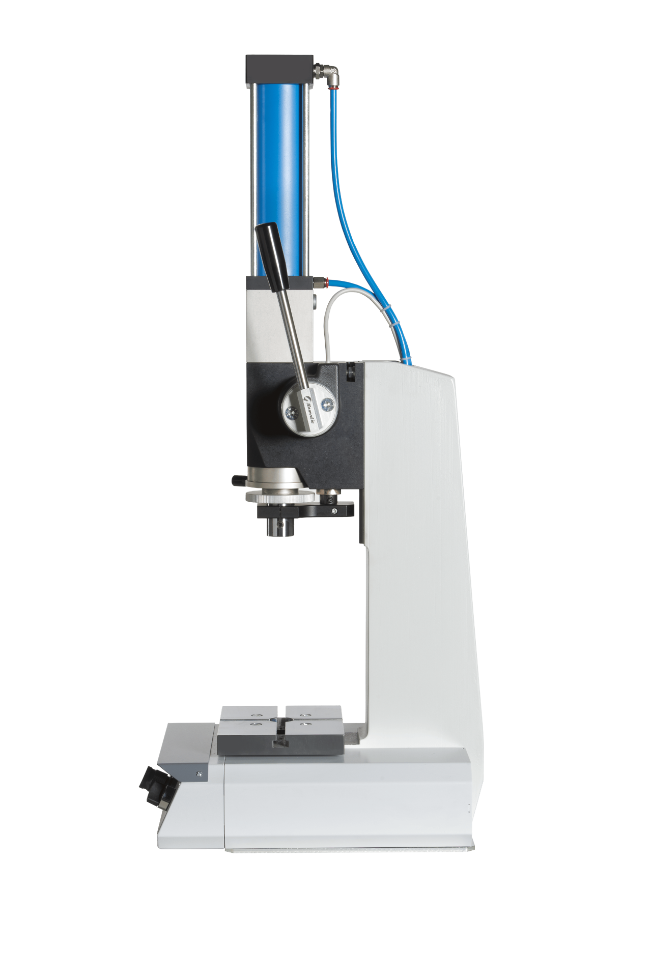
Low bending C-frame structure in Fe 430 B UNI 7070 steel with monolithic structure.


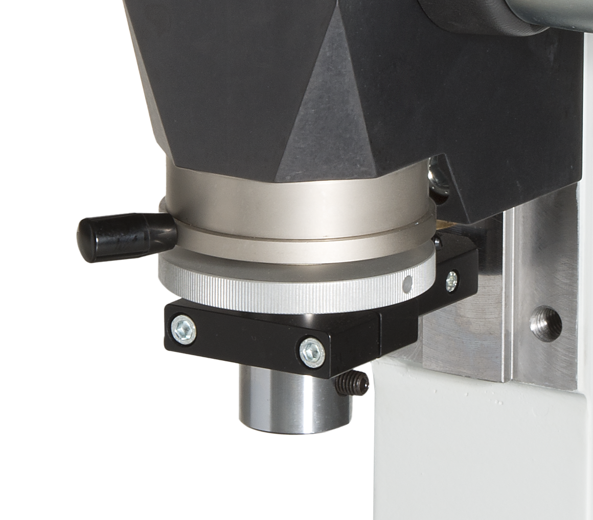
The bracket, in addition to the anti-rotation function of the press rod, allows to limit the return stroke of the rod (TDC).


It can be positioned in 4 points over 180 ° for greater working comfort. To change the position of the lever, unscrew and screw it back in the desired position.


For viewing and, if necessary, topping up the level of the hydraulic fluid.
Accessories and Options
End Stroke Mechanical Regulation
Device for micrometric adjustment of the final stroke of the rod (BDC)


Touch Button
Comfort version hand-guard side button, touch-sensitive


Single Power Unit
With manual or motor driven operation


Special Work Heights on Request
Special heights of work available on request


Force monitoring pressure switch
Allows pre-setting the pressure/force at which the press halts the pressing stroke.


The Controls
The presses can be equipped with electronic systems that monitor, piece by piece, the characteristics of the processing carried out.
They are based, depending on the model, on sensors for detecting the pressure/force and the position of the press rod.
Depending on the degree of accuracy, they are available in different configurations:


Press-Right
- a load cell, for force measurement
- a linear encoder, for position measurement
For the interface with the user, a 7,5″ display with 640 × 480 resolution in color, full touch, is available for easy use.


Check Point
Functions:
- Displays the expressed and peak force
- Stops the unit when the set force value is reached
Range and Technical Specifications
07 kN
1.4 kg
0.8 kg
0.4 kg
filtered air max 6 bar
60 / 100 mm
10 mm
90 mm / sec
176°
20 mm (tot 60) / 25 (tot 100)
0.164 nL
15 kN
1.8 kg
1.3 kg
0.5 kg
filtered air max 6 bar
60 / 100 mm
10 mm
65 mm / sec
176°
20 mm (tot 60) / 25 (tot 100)
0.349 nL
30 kN
2.2 kg
1.8 kg
1 kg
filtered air max 6 bar
60 / 100 mm
10 mm
40 mm / sec
176°
20 mm (tot 60) / 25 (tot 100)
0.636 nL
50 kN
2.4 kg
1.8 kg
1 kg
filtered air max 6 bar
60 / 100 mm
10 mm
30 mm / sec
176°
20 mm (tot 60) / 25 (tot 100)
1.098 nL
80 kN
2.4 kg
1.8 kg
1 kg
filtered air max 6 bar
60 / 100 mm
10 mm
30 mm / sec
176°
20 mm (tot 60) / 25 (tot 100)
1.888 nL
Download
Press MOP ita-eng catalog
26/02/2024
M-OP press manual - eng
26/02/2024
M-OP press manual - ita
26/02/2024
Manual M-OP presses - fra
26/02/2024
MOP press manual - esp
26/02/2024